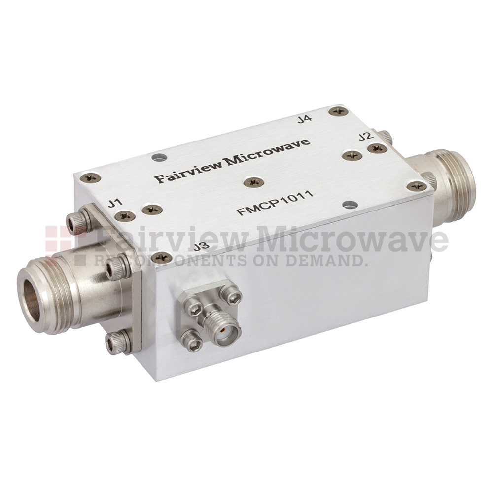
A directional coupler is a type of RF coupler that draws a small amount of energy away from the forward and/or reverse signal paths equally. As such, a RF directional coupler is a 4-port passive component with port 1 being the main input port, port 2 is the main output port, port 3 is the forward coupled, and port 4 is the reverse coupled port. An ideal directional coupler would not experience any loss throughout the system, would be perfectly matched at every port, and would be perfectly reciprocal. This means that an ideal directional coupler would have absolute isolation between ports, the coupler factor would be identical between ports 3 and 4, and hence the directivity would be infinite. Manufactured directional couplers cannot be ideally crafted and are made of materials with loss and tolerance variations, which is why all of these performance factors are relevant in the selection of a directional coupler for a given set of application requirements.
A directional coupler is generally described by the extent of coupling between the forward/reverse ports and the coupled ports in decibels of power. Common options are from 3 dB to 30 dB, though a directional coupler can be designed to have a coupler factor beyond this range. A directional coupler with a given coupling factor is chosen based on the strength of the forward/reverse signals and the desired minimal signal strength at the coupled ports. It is often the case that only either the forward or reverse signal path needs to be coupled, and a directional coupler has a matched termination on the forward or reverse coupled port. This termination can either be done during manufacture for a higher performance directional coupler or by using a matched termination at the port which allows for reconfigurability. This type of configuration is often what is meant by “directional coupler”. If neither port is terminated, this configuration is generally called a bi-directional coupler. The isolation of a directional coupler is dependent on how well the 4th port is terminated, which is often why a directional coupler comes with a factory termination made to quality standards.
There is another variation of a directional coupler, called a dual directional coupler, where there are two coupled paths that are terminated at their respective isolation ports. This configuration enables higher directivity and isolation between the ports, both forward and reverse signal coupling, and mitigates mismatch impacting directivity. However, dual directional couplers have higher insertion loss than a single directional coupler or bi-directional coupler.
Directional couplers in their various forms are very common components used in many applications from test and measurement to communications. Directional couplers are often integrated into test and measurement equipment designs and are also often used in a range of test applications. For instance, a directional coupler can be used as a reflectometer, which can measure the reflected signal energy from a load and monitor VSWR. With a directional coupler installed such that the output of a signal generator is measured, this approach can be used with a feedback network for actively leveled generation. There are also many other more complex test configurations possible, which is why directional couplers are common in used for monitoring critical signal paths within a system.


