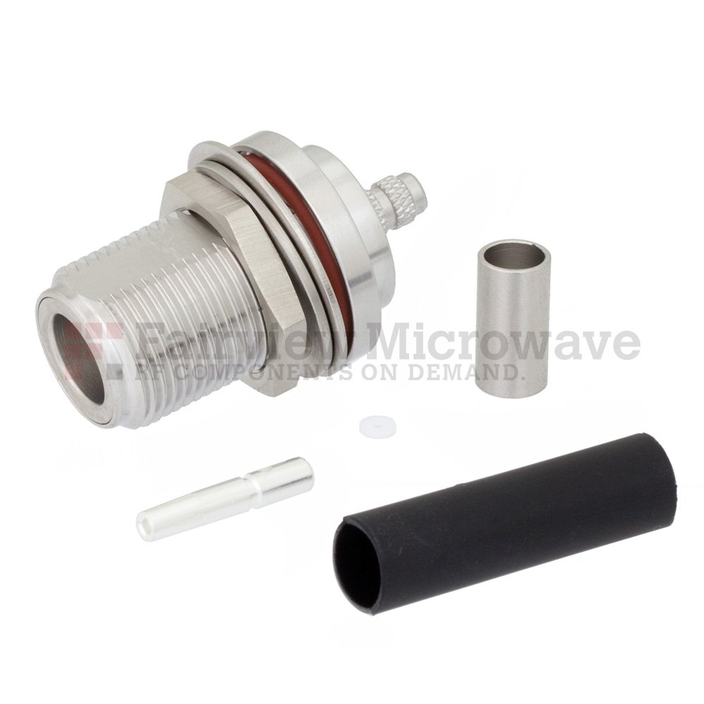
The diversity of RF and wireless applications has driven the diversity of RF coaxial connectors. For essentially all RF applications, there is an RF coaxial connector. It is impossible to cover everything about RF coaxial connectors in a single blog, let alone a book. The goal with this blog is to merely provide a high-level understanding of the various parameters and general types/applications for RF coaxial connectors.

RF Coaxial Connector Basics
The basic structure of an RF connector is an inner conductor, a dielectric insulator, and an outer conductor. Given the necessity to attach an RF connector to an RF coaxial cable, the RF connector inner conductor also has a method of attaching to an RF cable via the contact. The RF connector outer conductor, sometimes referred to as shielding, also has a method for connecting to the RF outer conductor/shielding of the RF cable, known as the body, attach. There are various methods of attaching an inner conductor/contact to a cable, and the same goes for the outer conductor/body, and these methods are important for various applications to ensure a desired level of ruggedness or reliability.
How two RF connectors “mate” determines the “gender” of the connector, either male, female, or in special cases, hermaphroditic. A male or a “plug” coaxial connector has a center pin that inserts into the female or “jack” connector. This is sometimes confusing with RF connectors, as the external thread is typically on the female/jack connector where the internal threading is on the male/plug connector. This could also be reversed, depending on the polarity of the RF connector. The configuration previously described is known as “standard” polarity and reverse polarity is the opposite.
There are also various mounting methods for RF connectors. For instance, panel/flange mount, or bulkhead, connectors connect to a solid conductive wall with a passthrough for the center pin to connect internal electronics through the bulkhead. Other types included PCB mount of many kinds, and even reusable end launch connectors.
A combination of the geometry and dielectric materials used determines the impedance of the RF connector, which are generally 50 Ohm or 75 Ohm nominal. There are other common impedance standards, but 50 Ohm and 75 Ohm are the most common.
RF Connector Type Specifications
- Connector type
- Gender
- Connector body
- Polarity
- Impedance
- Mounting method
- Attachment method
- Insulation material
- Body/outer conductor material/plating
- Contact/inner conductor material/plating
- Physical dimensions
RF Coaxial Connector Performance & Applications
A RF connector is simply coaxial conductors and insulators with several additional layers and structures to ensure performance under a range of use cases. The dimensions of the inner conductor, outer conductor, and dielectric determine the electrical characteristics of the connector, but also have bearing on the mechanical and environmental performance of the connector. For instance, a RF connector with a lower maximum frequency is physically larger with greater conductor spacing than a connector with a higher maximum frequency and will likely have a higher maximum voltage and maximum power handling.
Some specialized applications require extremely high-quality connectors with minimal insertion/return loss (i.e., excellent VSWR), such as RF test connectors. Other applications require a specific parameter to be optimized, such as low passive-intermodulation (PIM) connectors used for certain communications interconnect applications.
RF Connector Performance Specifications
- Maximum frequency
- Impedance
- VSWR
- Insertion loss
- Return loss
- Maximum Voltage
- Maximum Power handling
- PIM Response
Some applications drive the design of an RF connector in several ways. For instance, Hi-Rel RF connectors must meet an array of military specifications (MIL-Spec), which range from materials used in construction, fabrication process, quality control, as well as environmental performance parameters. While some applications focus more on certain performance criteria and may not need to meet any specific standard. This is why there are such a wide range of RF connectors available.
Common RF Connector Applications
- Hi-Rel (military, defense, government, and aerospace)
- RF Test & Measurement (T&M)
- Satellite Communications
- 4G/5G Cellular Communications
- Broadcast
- Wi-Fi/IoT Wireless Communications
- Medical
- Transportation
- Data Centers
- Building Automation
- Energy


