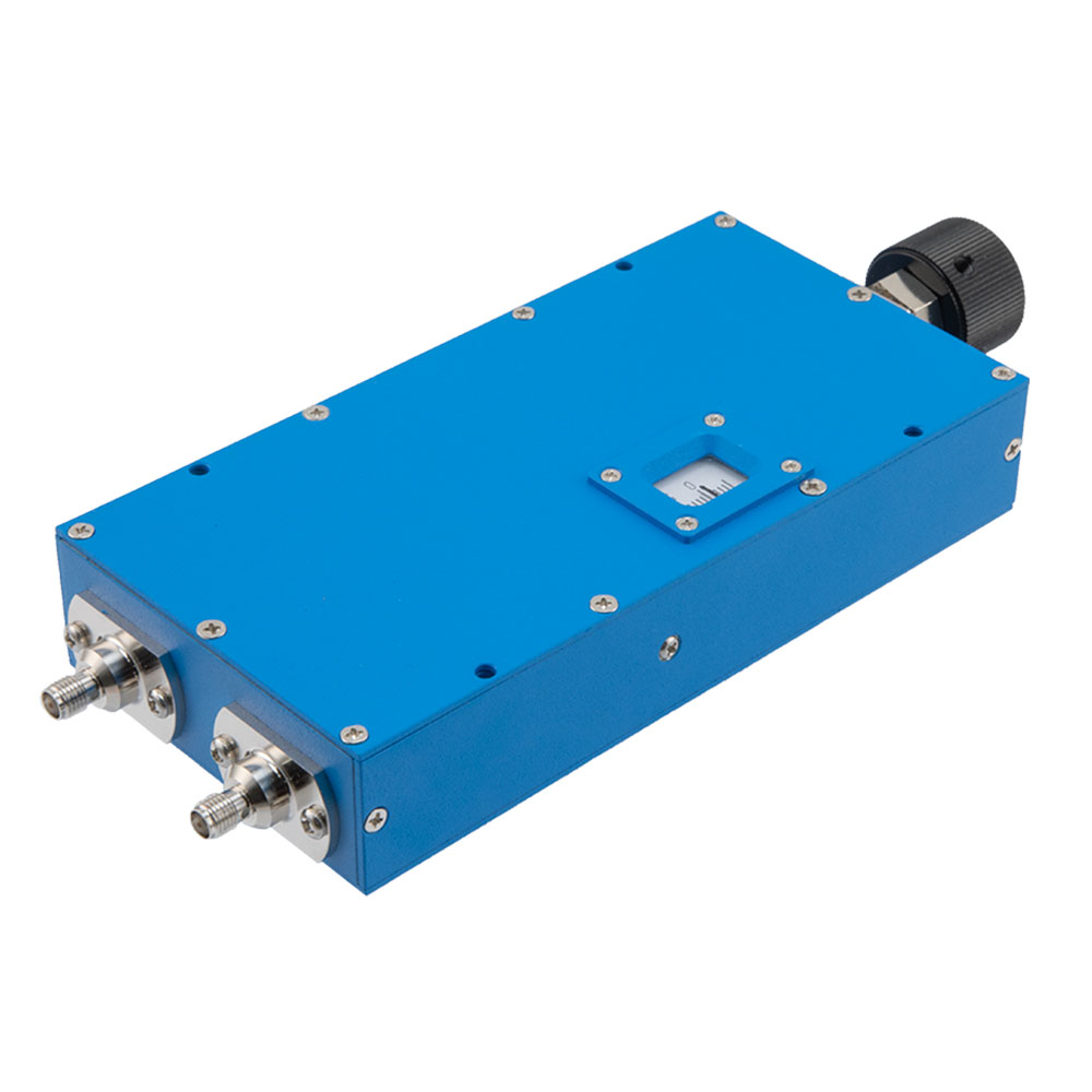
RF Phase Shifters are increasingly used in modern telecommunications, radar, and sensing systems for their key ability to shift the phase of in the input signal by a set amount, an adjustable amount, or a programmable amount, The basic utility of an RF Phase Shifter is that the device adjusts the phase of the output signal referenced to the input signal. This is essential in advanced/active antenna systems (AAS), active electronically steered array (AESA) antennas, and in a variety of other RF designs. An example of a non-antenna application for RF Phase Shifters is the cancelation loop in some high linearity amplifier designs or in IQ modulators/demodulators.
In general, RF phase shifters are linear two-port devices, many modern phase shifters have a manual/mechanical adjustment, analog, or digital method of adjusting the phase. These are either Analog Phase Shifters, RF Variable Phase Shifters, or RF Programmable Phase Shifters. There are also fixed phase shifters that are used in some applications. The total phase shifter through a phase shifter is the sum of the phase shift of the signal passing through the phase shifter as well as the phase shift from the phase shifting elements of the phase shifter. There are many varieties of phase shifting elements. Many modern phase shifters use solid state devices, such as varactor, PIN, or Schottky diodes, or for higher power applications ferrites are still used.

Analog phase shifters typically describe a class of phase shifters that have a continuously variable phase shift based on the control input. This effectively results in “unlimited” resolution and monotonic performance. Digital phase shifters, on the other hand, often employ switches to swift between various phase shifter states or use digital-to-analog converters (DAC) to drive analog phase shifters. This results in a set phase shifter resolution.
Key RF Phase Shifter Characteristics
- Frequency range or bandwidth (Hz)
- Phase shift(degrees or radians)
- Insertion loss or gain (dB)
- Return loss (dB)
- Group delay (ps)
- VSWR
- Linearity and/or harmonics: IP3 or P1dB (dBm)
- Phase accuracy (%)
- Phase resolution (degree)
- Amplitude modulation and/or phase modulation error (dB)
- Noise figure (dB)
- Impedance (Ohms)
- Input power handling continuous wave and/or peak (dB)
- Controllable and control type (fixed, analog, manually adjustable or variable, programmable, etc.)
- Bias voltage (V) and/or current (A)
- Control voltage range (V)
- DC power consumption (W)
- Reliability (cycles or mean-time between failure (MTBF))
- Switching time (ms, us, or ns)
- Phase voltage sensitivity (degrees phase shift/V)
- Insertion phase temperature stability (degrees phase shift/degrees celsius)
- Carrier suppression (dB)
- Side band suppression (dB)
RF Phase Shifters can be found as coaxial connectorized packages, waveguides, surface mount technology (SMT) components, through hole components, or integrated directly into assemblies or modules as die. Phase shifters can be fabricated from discrete components or even be fully integrated. Given the performance constraints, class III/V semiconductors, such as gallium arsenide (GaAs) and indium phosphide (InP) are often used as the semiconductor for analog or programmable phase shifters.


