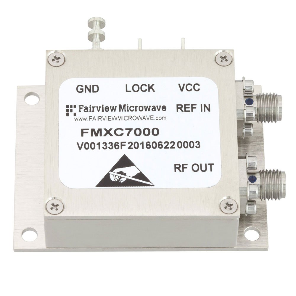
Phase-locked-loops (PLLs) are important components in many radio communication links and test equipment that rely on quality internal signals. PLLs are used in local oscillator (LO) circuits and RF Frequency Synthesizers that are designed to maintain precision frequency stability. In essence, a PLL provides a controlled output signal that is the comparison of the phase of a reference signal to the phase of a feedback signal. The output control signal of the phase comparison circuit in a PLL is used to adjust the input of a variable oscillator, and hence eliminate the error of the PLL output to a precise frequency. This is where the name phase-locked comes from. When the steady state output of the phase error detection circuitry is zero, the output frequency and phase are “locked” to the reference frequency and phase.

A PLL is composed of a phase detector, phase error detection, filters, variable/voltage-controlled oscillator (VCO), and a frequency counter/feedback divider. In this way, a lower frequency control signal can be used as a reference for a higher frequency output dictated by the capability of the VCO.
If a PLL is composed of linear elements and analog phase detector, loop filter, and VCO, then the PLL is an analog, or linear PLL. If any of these components are digital, then the device is a digital PLL. If the entire PLL is built of digital components that the device is an all-digital PLL. If a PLL is abstracted to the point that it turns entirely in the software of a digital signal processor (DSP), field-programmable gate array (FPGA), or application specific integrated circuit (ASIC) then it is a software PLL.
Virtually any device or system that requires a stable high frequency source can benefit from a PLL. Examples include wireless communication transceivers, radars, satellite communications, etc. A common use for PLLs in test and measurement equipment is to ensure the frequency generators of the test equipment provide stable and high precision outputs, such as with vector network analyzers (VNAs) and frequency generators/synthesizers.
Key Specifications & Features of PLL Frequency Oscillators and Synthesizers
- Frequency range [Hz]
- Load Impedance [Ohms]
- Output Power [dBm]
- Step size [dB]
- Hopping Time [ms]
- Phase locked speed [ms]
- Phase Noise (@ 100 kHz offset) [dBc/Hz]
- Spurious Rejection [dBc]
- 2nd Harmonic [dBc]
- Reference Frequency [MHz]
- Reference Power (continuous wave) [dBm]
- Internal Reference Frequency [MHz]
- Internal Reference Accuracy [ppm]
- Internal Reference Phase Noise (@ 1 kHz offset) [dBc/Hz]
- Operating DC Current [mA]
- Operating DC Voltage [V]
- Communication Interface [SPI, USB, TTL, etc]
- Reference & Output Connector type
- Temperature range of operation [deg C]


