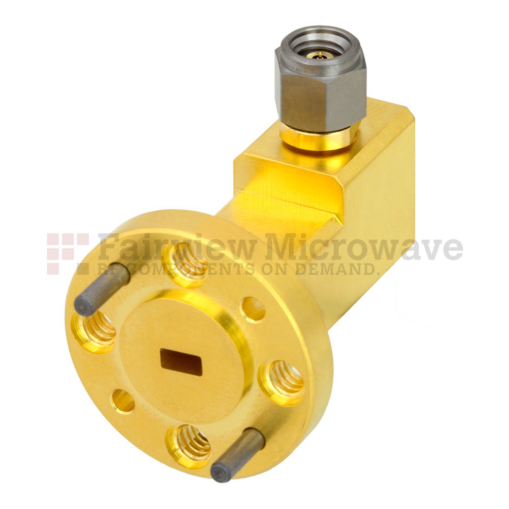
Outside of board-level RF interconnect, waveguides and coaxial interconnect are the most common types of RF interconnect. Waveguides are typically used with higher power, higher fidelity, and higher frequency banded applications. Coaxial transmission line interconnect is much more common in many applications as it is more readily fabricated into flexible or semi-flexible sections, and still provides moderate transmission performance and can more readily be connected/disconnected than waveguide.
In some highly complex or mixed high-power/high-frequency systems there is a mix of coaxial and waveguide interconnect. In these cases, there is a need to adapt between waveguide and coaxial standards. The most common way of doing this is by using Waveguide to Coaxial Adapters.
An example application could be that a coaxial transmission line needs to be connected to a rotating antenna structure, such as a rotating radar. In this case, a waveguide to coaxial adapter may be used to mate a rectangular waveguide to a circular waveguide rotary joint, and back again within the rotating antenna structure. Another situation may be that a high-power waveguide path has a directional coupler with low enough power coupled ports that using a coaxial transmission line is viable and eases routing considerations.

These adapters typically have a coaxial port, either male or female, at a 90-degree angle to the waveguide flange. The reasons that the coaxial connector is at a 90-degree angle is that the coaxial center conductor is generally the probe that extends into the waveguide and couples the electromagnetic energy between the coaxial TEM mode transmission in the coaxial connector and the waveguide modes in the waveguide. The coaxial center conductor probe is inserted into a rectangular waveguide perpendicular or parallel to the maximum E-field of the rectangular waveguide’s TE10 mode. The depth of the probe and the geometry of the probe are designed such that the EM fields radiated or coupled into the waveguide are optimized and avoid creating higher order waveguide modes. The opposite end in respect to the waveguide flange of a waveguide to coaxial adapter is a short circuit designed to a quarter wavelength of the desired center frequency of the waveguide to ensure radiation in only one direction.
As coaxial interconnect tends to have lower power handling than waveguide at the same frequencies, it is important to note that the coaxial interconnect is likely to be the limiting factor in a waveguide to coaxial adapter’s power handling specification. Also, since waveguides are “banded” meaning they have an upper and lower frequency band, and coaxial transmission lines have only an upper frequency limit, then the waveguide will likely be the limiting factor in the lower frequency specification of the waveguide to coaxial adapter.
Waveguides also tend to be physically larger than coaxial transmission lines until upper millimeter-wave frequencies.


