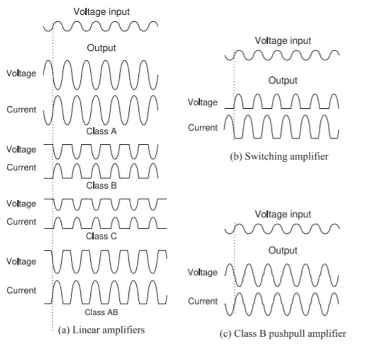
There are a variety of classes of RF Power Amplifiers that exhibit features that may be more desirable for certain applications. The main RF power amplifier critical features of efficiency, power output, gain, and linearity are not the only key characteristics but are heavily constrained by the amplifier class chosen. Amplifier class is a distinction made based on how the amplifier output stages influence the output signal over a full rotation of the cycle based on a sinusoidal input.
Classic controlled conduction angle amplifiers (linear amplifiers), including classes A, B, AB, and C, are defined by the duration of the conduction state over a designated portion of the waveform. The transistors in these amplifier classes are either fully on or off. These are the most common amplifier classes for use with optimizing the fidelity of the signal is most essential.
There is another set of amplifier classes, that being switching amplifiers, classes D, E, F, G, S, T, and others. The amplifiers in this class are switched rapidly using pulse width modulation (PWM), which leads to a hard driven output well into the output stage transistor’s saturation and cut-off regions. The goal of these switched functions are to switch when there is essentially zero current when their is voltage across the transistor and at zero voltage when there is current across the transistor. These classes can be configured to be the most efficient, but at the cost of signal quality (mainly linearity and noise) and complexity. Due to the complexity of these amplifier types they are more commonly found in highly integrated solutions that allow for more complex bias and control circuitry and benefit from the high level of efficiencies achievable by these classes.

image source https://eng.libretexts.org/Bookshelves/Electrical_Engineering/Electronics/Microwave_and_RF_Design_V%3A_Amplifiers_and_Oscillators_(Steer)/04%3A_Power_Amplifiers/4.03%3A_Switching_Amplifiers_Classes_D_E_and_F
Class A Amplifiers
Class A Amplifiers are the simplest amplifiers that use just one transistor in the output stage with the transistor output biased around the quiescent point (Q-point) in the center of its load line. In this way the class A amplifier can be biased so as to avoid being driven into cut-off or saturation, and can output the full conduction cycle. This class is hence extremely linear, low distortion, and high gain, but at the cost of efficiency.
Class B Amplifiers
Class B Amplifiers have an output stage of complementary transistors that each output only half of the waveform (push-pull amplifier). As these amplifiers don’t need to be biased around a Q-point, they use less DC power and are more efficient than class A amplifiers at the cost of linearity, distortion, and complexity of design.
Class AB Amplifiers
Class AB Amplifiers are a hybrid class where the output amplifiers both conduct around the waveforms crossover point, which eliminates crossover distortion, which is the main drawback in linearity performance of class B amplifiers. These amplifiers are common in RF power applications, as they are more efficient than class A and more linear than class B.
Class C Amplifiers
Class C Amplifiers are biased such that the output current is zero for more than half of the signal period. This is a much more efficient approach than class A, B, or AB amplifiers, however it is the most prone to distortion. However, these amplifiers are often used in high frequency oscillator circuits, where the class C amplifier output pulses can be converted to sine waves using LC resonant circuits.
Learn more about RF Amplifier Types in this blog post.


