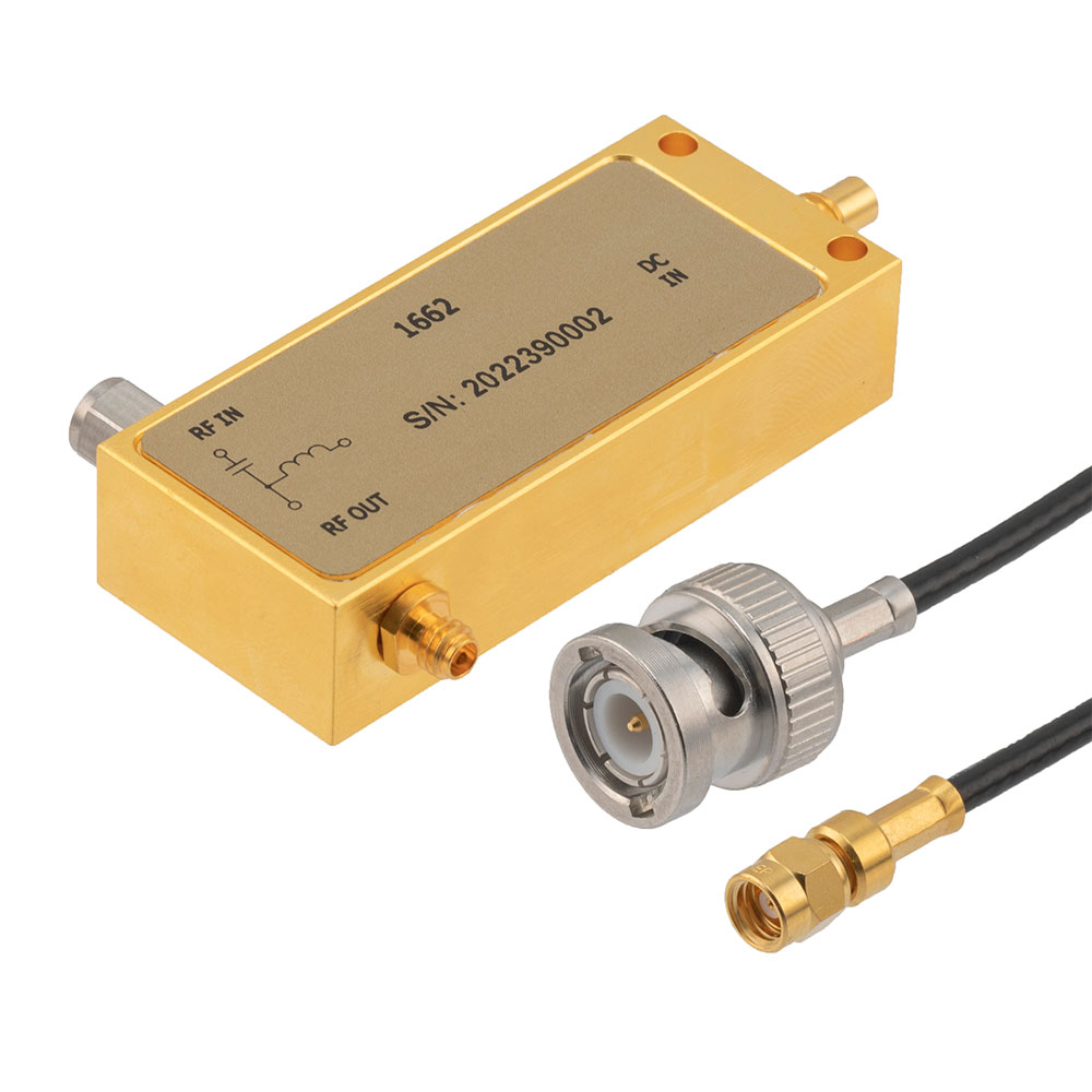
RF Bias Tees are essentially three-terminal diplexers that allow for very low frequency pass through from an input RF port to a dedicated DC port, while blocking the DC from passing to the RF output port. This assumes that the incident energy at the RF input contains both DC and RF energy. Hence, the three terminal network is a high-frequency and low-frequency input port, a low-frequency output and a separate high-frequency output. The basic circuit model for an RF Bias Tee is the input port that splits into two paths, a high-frequency bath with an ideal capacitor that blocks all DC energy to the RF port, and a low-frequency path with an ideal inductor that blocks all high-frequency energy to the DC port. In reality, broadband Bias Tees are more complicated than this. In part this is because most Bias Tees are coaxial connectorized components and the impedance of the coaxial transmission lines must also be taken into account.
Because of parasitics and design limitations, Bias Tees have additional inductors, capacitors, and resistors that may present a frequency operation that is the limiting factor in the performance of the Bias Tee, as opposed to the upper frequency limit of the coaxial interconnect used in the connectorized package.

Bias Tees can be used to either inject DC bias power into the RF signal line, or to extract DC power from an RF signal line. This is typically done when it is convenient to transfer DC power and RF signal along a transmission line to remote active devices, such as antenna amplifiers located near the antenna to avoid signal loss through relatively long runs of transmission lines. Powering remote active electronics could also be accomplished by running additional DC power feeds, but there are often expense, regulation, and reliability concerns with this approach which justify the cost and installation of Bias Tees.
It is important to note that as many Bias Tees have a variety of capacitive, inductive, and resistive elements, that there are naturally a variety of resonances that result in RF performance that deviates from an ideal transmission line. This could include higher loss at certain specific frequency ranges, or otherwise limited insertion loss flatness over the frequency range of operation.
Main RF Bias Tee Electrical Parameters
- Frequency range (Hz)
- RF port VSWR
- RF to bias isolation (dB)
- RF input power (dB)
- DC voltage (V)
- DC current (A)
- DC power maximum (W)
- Impedance (Ohms)
- Insertion loss (dB)


