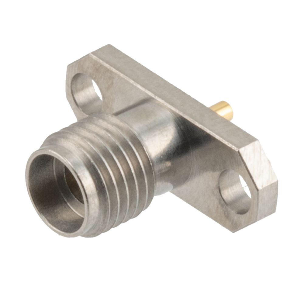
With the increasing number of millimeter-wave applications, there is a growing demand for coaxial connectors that can be mounted directly on a PCB, or other laminates, and mounted on the outside of a housing and still connect through to a PCB or internal lead/coaxial line. For millimeter-wave applications, such as radar, satellite communication, military/defense, aerospace, and the latest in telecommunications with 5G or millimeter-wave Wi-Fi, compact coaxial connector types are necessary as the geometry of a coaxial connector directly impacts the frequency performance of these components.

The most common coaxial connectors for millimeter-wave applications are 3.5mm (26.5 GHz/34 GHz max and 45 W max continuous), 2.92mm ( 40 GHz max and 20 W max continuous), 2.4 mm (50 GHz max and 15 W max continuous), and 1.85 mm (60/67 GHz max and ~10 W max continuous). There is some discrepancy among manufactures of various coaxial connector types of the maximum frequency, as this depends on construction, materials, and tolerances. Hence, there are typical coaxial connectors that are made to the standard specifications and precision connectors which exceed the standard specifications in design and performance.
Common PCB Mount Coaxial Connector Variations
- End Launch with Round Contact
- Solder Attach Thru-hole Round Contact
- Surface Mount with Round Contact
- Solderless PCB Mount 2 Hole Flange Round Contact
- Solderless PCB Mount 2 Hole Flange Contact Ring Without Gap
- Solderless PCB Mount 2 Hole Flange Contact Ring with Gap
- 2 Hole PCB with Narrow Body End Launch
- 30-degree Angle Solderless PCB Mount 2 Hole Flange Round Contact
In order to test or otherwise direct signals that are generated on, or intended for processing, on a PCB, it is essential to have a coaxial connector that brings the coaxial interconnect environment to the PCB or other laminate. On a PCB the interconnect are often planar transmission lines or even vertical transmission line types, but in order to connect a board to another board or other systems, coaxial transmission lines are usually the most common choice. These connectors can either be directly soldered and mounted to the PCB in vertical, right angle, or end launch configurations. Another option is to use some type of clamping mechanism to force the mechanical and electrical connection of a solderless connector to the PCB conductors.
Common Bulkhead/Flange Mount Coaxial Connector Variations
- 2 Hole Flange with Round Contact
- 2 Hole Flange with Contact Ring without Gap
- 2 Hole Flange with Contact Ring with Gap
- 4 Hole Flange with Round Contact
- 4 Hole Flange with Solder Cup Contact
To channel signals in and out of a housing, bulkhead and flange coaxial connector types are used. These connector types either have a 2/4-hole flange with screw hole patterns for attaching the connector to a conductive housing or another type of threaded fixture. Contact rings w/wo gaps and solder cup contacts are the most common type of bulkhead/flange coaxial connector center pin connection type.


